| Learning Aims: |
|
| Materials: |
|
Variable power source (up to 10V), leads, computer, interface and software (e.g. CMA Coach6), current sensor, voltage sensor, temperature sensor (if computer with interface is not available, ammeter and voltmeter and thermometer can be used), metal conductor (e.g. a long thin copper wire), thermistor |
| Suggestions for use: |
|
Divide the class into small groups of 2-3 and hand out Classroom Material: Resistance and temperature. In this activity students carry out an experiment in order to investigate the relationship between the resistance of a resistor (thermistor) and its temperature. The resistance is measured via measuring current flowing through the element and voltage across it calculating the corresponding resistance. At this stage students should be confident enough in measuring current and voltage as well as the temperature with the help of sensors. The main idea is to find out the main difference between the metals and semiconductors in terms of the temperature dependence of their resistance and understand that based on this dependence the element can be used as a device for measuring temperature.
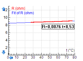
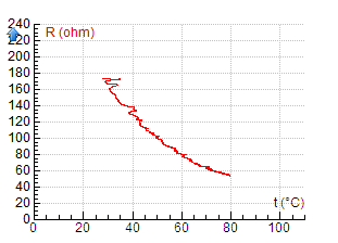
Fig. Experimental results for metal Since the temperature coefficient of resistance for metals is rather small (alpha is typically from 3*10-3K-1 to 6*10-3K-1 ) we need a long thin wire to have the initial resistance big enough to see the difference when heated. In case we do not have an appropriate wire available, students can use the results measured already in COACH 6 that they can analyse. (the file Resistance and temperature_metal.cmr.) The resistance temperature dependence for a thermistor is much more significant with negative temperature coefficient of resistance. The result can be seen in the file temperature_metal.cmr. In both cases students carry out measurement and the following analysis in a guided inquiry mode. The ready-made result can be used in case of lack of time but real measurement is preferable. In both cases the analysis should lead to the data fit that is linear for the metal but much more complicated for thermistor. We introduce the idea of the temperature calibration. For students who are already familiar with the exponential function the thermistor calibration can be done. So, at the end, students get the thermistor calibrated for temperature measurement. They can compare their thermometer with data from the temperature sensor.
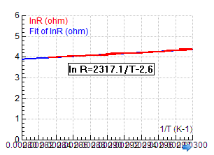
Fig. Example of thermistor calibration result The important point is to get the idea about the principle of resistance thermometer and its calibration. The connection with industry can involve information about resistance thermometers and thermistors and their applications (thermistors in automotive industry for monitoring the coolant and oil temperature in the engine, temperature of the incubator, etc.). |
| Possible Questions: |
|