The aim of the Activity is to build a measuring tool – a colorimeter. The constructed device will serve for performing Activity s II.2 and II.3, and its construction is the introduction to the Activity IV.3. Alternatively, a commercial colorimeter can be used (for example:http://www.vernier.com/products/sensors/col-bta/)
Equipment:
- Contact plate (electronic breadboard)
- RGB LED 5 mm
- Photodiode 5 mm
- Resistor 220 W - 3 pieces
- Resistor 1MW
- 3-channel (or more) programmer
- Voltage regulator - 7805 IC
- 9 V battery
- 9 V battery connector with cables
- Cables
- Superglue (quick-drying glue)
- Plasticine
- Cable cutters
- Tweezer
- Cuvette
- Multimeter
- Cuvette holder – see description below
- Aluminium tubes
- Self-adhesive felt or rubber veneer.
Description of the structure:
The whole device is built on the contact plate. The plate provides a base for the next parts as well as an easy connection of resistors and other components without soldering. The plate provides the connection between elements placed in the vertical and horizontal lines of contact regions.
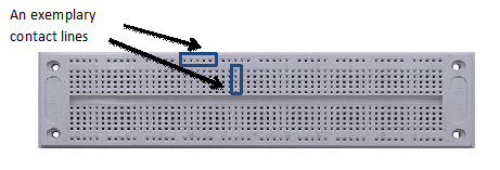
Figure III.1. An sample contact plate (or ’breadboard’).
Cuvette holder preparation:
A role of the cuvette holder may be played by any rectangular box with a matching lid. A convenient solution is the use of rectangular aluminium tubes of: 1. 20 mm and 2. 25 mm diameter.
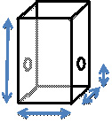
Figure III.2. A diagram of the cuvette holder.
- Cut off the piece of tube:
- 1. about 4 cm in length – being a holder for the cuvette
- 2. about 1,5 cm in length – being a lid for the holder.
- In the tube No. 1, drill 2 holes of a 8 mm diameter at a height of about 1,5 cm.
In case of difficulties in working with the aluminium tubes, a plastic or cardboard box (e.g. a match box) may be used.
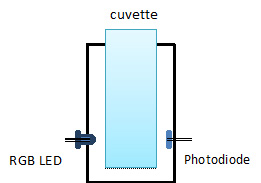
Figure III.3. A diagram of the cuvette holder with the RGB LED and the photodiode installed.
- Wrap around the inner side of the holder with veneer, so that the cuvette fits the place for it in the holder,
- In the holder holes, install the RGB LED and the photodiode. At first, diodes are loosely inserted, so as to have an ability to connect them to contact plate then, their position is fixed with the use of glue.
- Place the cuvette holder on the contact plate.
A diagram of the colorimeter structure:
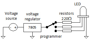
FigureIII.4. A diagram of the LED circuit.
Connecting the RGB LEDs
- Put a cuvette holder on the contact plate in about 2/3 of its length.
- Connect the RGB LED to the contact pins according to the diagram (Figure III.5).
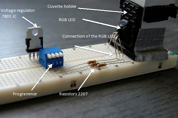
Figure III.5. Power and control system of the RGB LED connected to the contact plate.
The longest leg of the RGB LED is the output, the three others are inputs.
- Plug the legs of the LED into the contact plate according to the Figure III.5.
- After plugging, stiffen the LED position and stick the cuvette holder to the contact plate.
- Then, install the resistors 220 W according to Figure III.5/ III.6
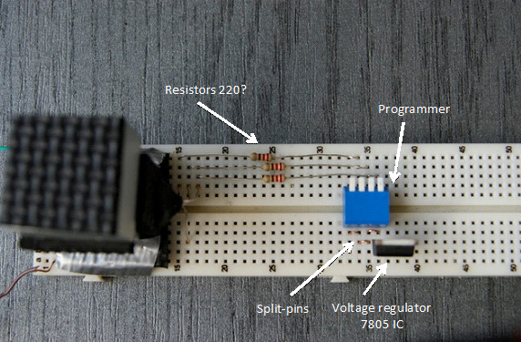
Figure III.6. The control system of the RGB LED connected to the contact plate, top view.
- Install the programmer – 3 joints of the programmer should correspond to the sites of resistors placing.
- From the other side of the programmer, connect all the channels with the split-pins (Fig.III.8).
- Install the voltage regulator in such a way, that the left leg supplies the voltage to the closed programmer channels.
- Connect the voltage regulator
- Connect the power supply (Figure III.7)
- Check the proper working of the system by turning on any programmer channel – the LED lightning should be observed.
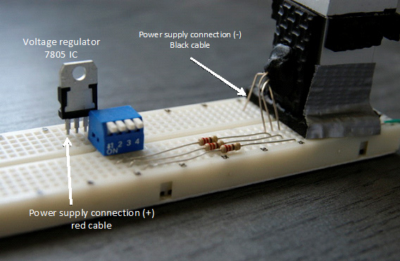
Figure III.7. The power supply connection.
Connecting the photodiode
- Place the photodiode in the cuvette holder (in the opposite side to LED diode).
- Attach two cables to the end of the photodiode – it is best to solder them.
- Plug the cables into the contact plate according to Figure III.8
Figure III.8. Connection of photodiode and multimeter.
- Install the resistor 1 MW between the photodiode channels,
- Plug the cables supplying voltage to the multimeter into the plate.
- Connect the multimeter – set the DC voltage measurement.
- Control the working of the photodiode – when the cuvette holder is closed and the light is turned off, the voltage should not be observed. The voltage should appear in the multimeter after switching on the light.
The device is ready to use.
Prepared device can be used as PC data logging device. Simple millimetre can be replaced by CMA CoachLab II+ interface and Coach 6 software. In the program the device must be added as new sensor and calibrated.
The shame of the device developed by: Jose H. Bergantin, Jr., and Fortunato Sevilla III University of Santo Tomas, Manila, Filippines